软件架构图和模式


软件架构是任何成功软件系统的基础,并且会影响整个系统生命周期中的可维护性、可扩展性、稳定性和安全性等方方面面。实现新软件系统的第一步是架构图。
随着软件系统和 Web 应用程序变得越来越复杂,精心设计的系统架构图对于与其他开发人员和利益相关者进行交流变得至关重要。软件架构图是一种重要的文档实践,可帮助您规划和实施网络中的更改、可视化战略计划并领先于组织的需求。
今天,我们将重点介绍如何绘制图表、流行软件架构模式的一些示例,以及找到参考架构的地方,以用作各种用例的起点。我们还将讨论一个好的架构图应该完成什么,以及为什么你应该花时间来创建一个。
让我们潜入水中!
我们将介绍:
- 什么是软件架构
- 图表基础:流程图、C4 和 UML 2.5
- 6 种软件架构模式
- 3 个用于构建应用程序的公共云平台
- 总结和后续步骤
什么是软件架构?
软件架构描述了系统在其环境、关系、设计原则等上下文中的基本概念和属性。软件架构包括软件系统的组织、结构元素、行为元素,以及将这些元素组合成更大的子系统。软件系统通常可以包含多种架构。
“没有考虑整体架构或设计的编程就像只用手电筒探索洞穴:你不知道你去过哪里,你不知道你要去哪里,你也不知道到底在哪里你是。”
丹尼·索普
拥有出色的架构为您将来如何处理性能、容错性、可扩展性和可靠性奠定了基础。为您的软件选择正确的架构将在您扩大规模时在压力条件下保持稳定的性能。
即使您预计用户数量不会增加,考虑您的计划的大局以及如何将该愿景传达给其他人也可以帮助您和您的团队根据这些决策对您整体的影响做出战略决策建筑学。
为了扩展丹尼·索普的洞穴类比,如果你的洞穴之旅出了差错并且你正在等待救援人员找到你,那么彻底绘制洞穴系统会产生巨大的影响。
同样,完善的软件架构可以帮助您的工程师快速定位和修复错误。
我们需要记录软件架构吗?
您是否应该记录您的软件架构取决于您正在处理的项目类型。关于记录软件架构是否真的值得花时间,或者它是否会减慢一切,存在一些争议。现实在中间的某个地方。
一些开发人员并不需要为每个项目设计一个映射良好的软件架构。如果您是单独工作或使用像敏捷这样专注于持续改进的固有适应性开发方法,则可能很难记录每一次更改。
“不正确的文档通常比没有文档更糟糕。”
伯特兰·迈耶
在其他时候,对复杂系统中软件架构的重要部分的记录不足可能会导致重大问题或导致技术债务。作为一般规则,一旦您的项目扩展到多人,您就应该开始记录产品的软件架构。
你需要记录什么?
您必须确保核心组件和高级架构可供每位员工使用。在许多情况下,软件架构及其文档将比产品的最初创建者更持久。从事产品工作的人可能会改变,使用的编程语言可能会改变,但软件架构几乎总是会保持不变。
这就是为什么记录您的软件架构如此重要的原因。它允许从事该项目的人员查看您的产品如何更改和发展的记录。
虽然您可能不想记录每个代码更改或架构更改,但您肯定希望记录重大更改,同样重要的是,记录进行这些更改的原因。
好的架构图能完成什么?
好的软件架构图是真实和清晰的来源。您希望您的图表能够快速向技术和非技术受众传达软件系统的基本组成和行为。
如果做得好,高级架构图和详尽的文档可以成为传达系统或应用程序内部状态的有效工具。
在开始编码之前绘制图表和在编写代码之后绘制图表也会带来不同的好处。
- 正向设计需要在您或您的团队开始编码之前创建图表。这有助于帮助您的开发人员更好地可视化他们正在尝试创建的系统。
- 后向设计涉及在编写代码后绘制图表。这可以帮助开发人员了解项目是如何开发的,并记录该工作流程以供以后改进。
“在编程领域,没有什么比无证程序更卑鄙的了。”
爱德华·尤登
您还希望您的图表尽可能不言自明,以便任何查看它的人都可以立即看到您的软件系统中的关系、约束和限制,而无需询问您的含义。
一个好的架构图将:
- 图表核心组件
- 突出关键系统交互和关系
- 易于访问和共享
- 保持一致的风格
- 更容易识别软件架构中的潜在缺陷或需要改进的领域
图表基础:流程图、C4 和 UML 2.5
既然我们已经谈完了记录软件架构如何使您受益,那么让我们看看一些用于制作图表的常用方法。
流程图
流程图是您可以制作的最基本的图表类型之一。它们的简单性使它们成为在开始编码之前可视化算法或程序逻辑的有效工具。
以下是流程图键的示例,其中包含图表中使用的一些常见符号。
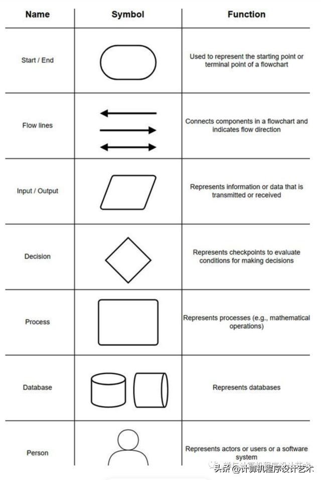
在技术图表中,每个形状通常包括以下内容:
- 被表示的元素的名称
- 该元素在系统中的作用
- 那个元素的技术
图表的每个组件都有将其连接到其他组件并描述它们之间的交互的箭头。
C4 型号
C4 模型是软件系统的体系结构文档标准,它将软件系统分为四个级别:
- 上下文(第 1 级):上下文图是对系统做什么、它解决什么问题、涉及的人员以及与之交互的任何外部系统的高级概念描述。这些图表有助于提供全局概览。
- 容器(第 2 级):容器图更深入地描述构成系统的应用程序或服务之间的高级交互。容器可以代表 API、数据库、文件系统、微服务等。
- 组件(第 3 级):组件图查看容器内的不同代码体。这些图表有助于可视化代码库的抽象。
- 代码(4 级):顾名思义,代码图着眼于映射到代码的架构元素,如类、接口、对象和函数。
作为最低要求,大多数团队应该为他们的软件系统创建和维护上下文和容器图。
如果组件图增加了价值,则可以创建它们,但您需要找到一种方法来自动更新这些图以用于长期文档目的。
大多数 IDE(或 UML 建模工具)可以按需生成代码图,因此这种详细程度的文档更容易检索而不是维护。如果一个组件特别重要或复杂,那么手头有 4 级图表可能会有所帮助,但在大多数情况下,您可以等到需要这些图表时再生成它们。
UML 2.5
统一建模语言 (UML) 最常用于软件工程,以创建用于记录 4 级架构元素的图表。
有 14 种类型的 UML 图分为两大类:
- 结构图显示了建模系统中的对象。
- 行为图显示了这些对象如何相互交互。
在本文中,我们将主要关注 C4 模型的第 1 级和第 2 级图,因此我们不会在此详细介绍。
但是,如果您想生成第 4 级图表,那么研究 UML 可能是一个不错的起点。
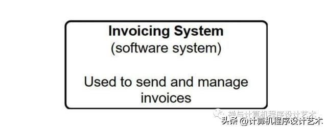
示例:发票系统
您正在构建一个 Web 应用程序,数字艺术家可以使用它来管理和向客户发送发票。这个的上下文图会是什么样子?
您的图表至少应包括:
- 数据库
- 业务逻辑组件
- 用户界面
首先,从您的软件系统的表示开始。
接下来,您要记录演员是谁。演员是任何将使用该软件系统的人。
在这种情况下,我们的演员是:
- 数字艺术家
- 客户
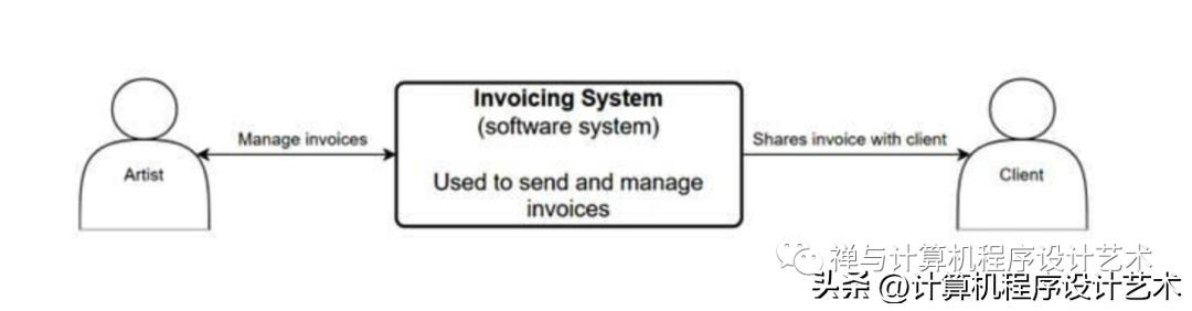
既然您知道您的参与者是谁,请记录与软件系统交互的任何外部系统。
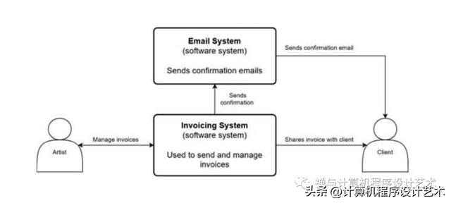
如果你想更深入,你可以创建一个容器图。容器图将关注构成特定容器的应用程序。
6 种软件架构模式
有许多软件架构风格,了解流行的风格可以为您节省一些时间。这是对六种不同类型的架构模式的基本(但希望是全面的)介绍。
1.分层(N层)架构
分层架构模式,也称为 N 层架构模式,是大多数 Java 企业应用程序使用的标准架构。分层架构风格将组件(或应用程序)划分为水平的逻辑层。
每一层在系统中都有不同的作用。一层可能负责处理业务逻辑,而另一层负责处理表示逻辑。这展示了一个称为关注点分离 (SoC) 的概念。层的组件将仅处理该层内的逻辑。像这样分离层也使测试和开发软件更容易,因为模式本身并不太复杂。缺点是这不是最有效的使用模式,而且很难扩大规模。
大多数分层架构将由四个封闭层组成:
- 介绍
- 商业
- 持久性
- 数据库
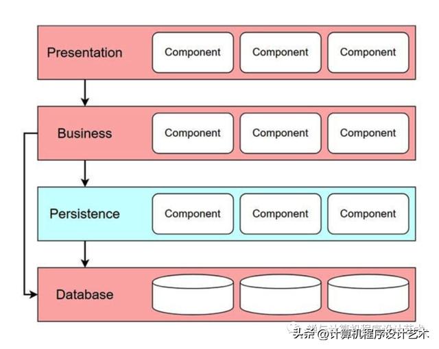
有时,业务层和持久层会合并为一个单独的层,尤其是当持久性逻辑(例如,SQL)包含在业务层的组件中时。较小的应用程序可以只有三层,而更复杂的应用程序可以包含五个或更多。
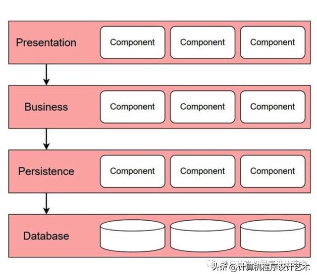
封闭层要求请求通过目标层之前的层。例如,如果您尝试向数据库层发送请求,则该请求必须首先通过表示层、业务层和持久层。
但有时,让请求通过每一层是没有意义的。对于这种情况,您可以打开某些层,以便请求可以跳过它们并直接转到它们下面的层。
对于大多数应用程序来说,分层架构模式是一种很好的通用模式,尤其是当您不确定要使用哪种架构模式时。
注意:层和层都是指软件系统的功能划分。但是,层是指在与其他部门分开的基础架构上运行的软件。因此,如果所有层都在同一设备上运行,则具有多个层的应用程序只能具有一层。
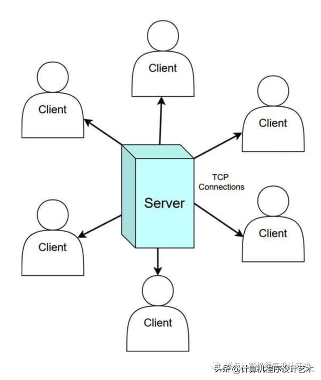
2.客户端-服务器架构
在客户端-服务器架构中,有多个节点或客户端通过网络或 Internet 连接与中央服务器通信。
有两种主要类型的组件:
- 发送请求的服务请求者(又名客户端)
- 响应请求的服务提供商
在这种架构中,服务器托管、管理和交付客户端请求的大部分资源和服务。这也称为请求-响应消息传递模式。
具有客户端-服务器架构的应用程序的两个经典示例是万维网和电子邮件。
3. 事件驱动架构
事件驱动架构模式是具有高度适应性的分布式异步架构模式。这种模式最适合具有高可扩展性的小型到大型应用程序。由于在此模式中事件处理器组件彼此隔离,因此可以对组件进行更改而不会影响其他组件的性能。
这种模式有两种主要的拓扑:中介和代理拓扑。
中介拓扑有四种主要类型的组件:
- 事件队列
- 事件中介
- 事件通道
- 事件处理器
当事件具有多个步骤,需要通过中央调解器进行某种程度的协调以进行处理时,使用调解器拓扑。
当用户将初始事件发送到事件队列时,初始事件将被定向到事件中介。
接收到初始事件提示事件中介者发布和发送处理事件到事件通道,告诉他们开始执行每个流程步骤。从事件通道接收处理事件的事件处理器包含执行处理初始事件所需的所有步骤的业务逻辑组件。
一般来说,事件处理器组件应该只执行单个业务任务,而不依赖于其他事件处理器。这是因为您希望您的事件处理器能够与其他事件处理器同时运行步骤。
代理拓扑用于事件不需要中央调解器来分发或协调事件的流程。
代理拓扑有两种主要类型的组件:
- 经纪人
- 事件处理器
代理组件包含此事件流的所有事件通道。这些事件通道可以是消息队列、消息主题或两者的组合。
在代理拓扑中,事件处理器组件直接接收事件并负责处理和发布新事件以指示事件已被处理。
事件不断地流经处理器组件链,直到不再为初始事件发布事件。
这种进程分布允许事件驱动架构以最少的资源消耗运行大量并发连接。
4.微内核架构
微内核架构(也称为插件架构)通常用于实现可作为第三方产品下载的应用程序。这种架构也常见于内部业务应用程序中。
这种架构的一个有趣之处在于,您实际上可以将其嵌入到其他模式中,例如分层架构。
在典型的微内核架构中有两种架构组件:核心系统和插件模块。
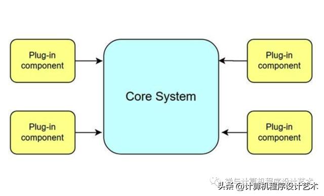
核心系统包含使软件系统运行所需的最小业务逻辑。您可以通过连接插件组件来扩展软件系统的功能以添加更多功能。
这有点像为您的汽车添加冷空气进气口以提高其扭矩和马力。
可以使用开放服务网关倡议 (OSGi)、消息传递、Web 服务或对象实例化来连接插件组件。实施方法由您决定。
注意:插件组件是独立的组件,旨在扩展或增强核心系统的功能,不应与其他组件形成依赖关系。
5.微服务架构
微服务架构是目前最流行的软件趋势之一,其中一个原因可以归因于开发的易于扩展性。当微服务无法再维护时,可以重写或替换它们。
术语“微服务”没有普遍接受的定义。在本文中,我们将微服务定义为可独立部署的模块。
微服务架构由具有小型代码库的小型、独立、自包含服务组组成。与使用分层架构模式的单体应用程序不同,保持小的、独立的代码库可以最大限度地减少依赖项的数量。
微服务架构的每个组件都部署为一个单独的单元。单独部署单元简化了交付管道并使部署速度更快。开发团队可以轻松地建立具有较小单元的持续交付管道。测试也变得更容易,因为您只需要测试单个微服务的功能。
注意:微服务架构仅在部署自动化时才有效,因为微服务显着增加了可部署单元的数量。
微服务架构的另一个关键概念是服务组件。服务组件的复杂程度可以从单个模块到应用程序的大部分。微服务架构被认为是一种分布式模式,因为它们的服务组件彼此完全解耦。
微服务还有助于持续交付,这有助于使软件开发更加灵活。
亚马逊、Netflix 和 Spotify 等大公司都在实施这种架构。
6. 云原生架构
当您考虑典型的 Web 应用程序时,它们中的大多数通常以相同的方式处理来自客户端的请求。客户端从 Web 浏览器发送请求,该请求被发送到 Web 服务器,然后是应用程序服务器,最后是数据库服务器。当这种数据流处理大量并发运行的请求时,您通常会遇到瓶颈问题。这就是云原生架构模式的用武之地。云原生模式旨在通过删除中央数据库并使用复制的内存数据网格来最大限度地减少可伸缩性和并发相关的问题。
云原生架构主要用于分布式计算系统,其中组件之间的交互通过一个或多个共享空间进行调解。
在这个共享空间中,组件交换元组和条目。这给我们带来了元组空间的概念,或分布式共享内存的概念。
元组空间提供可以同时访问的元组存储库。应用程序数据保存在内存中,并在活动处理单元之间复制。
此架构模式中的两种主要组件类型是:
- 处理单元
- 虚拟中间件
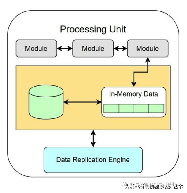
处理单元通常包含:
- 应用模块
- 内存数据网格
- 用于故障转移的可选异步持久存储
- 数据复制引擎
数据复制引擎是虚拟中间件用来将一个处理单元中所做的数据更改复制到所有其他活动处理单元的工具。
虚拟化中间件管理请求、会话、数据复制、分布式请求处理和流程单元部署。
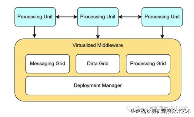
虚拟化中间件将包含四个主要组件:
- 消息传递网格
- 数据网格
- 处理网格
- 部署经理
消息传递网格是管理输入请求和会话信息的组件。
数据网格是虚拟中间件中最重要的组件,它与每个处理单元中的数据复制引擎进行交互。
部署管理器是根据负载条件管理处理单元的启动和关闭的组件。当用户负载增加时,它将启动新的处理单元,当用户负载减少时,它将关闭处理单元。这种对不断变化的环境的动态响应允许基于空间的应用程序轻松扩展。
处理网格是一个可选组件,当多个处理单元处理应用程序的一部分时,它管理分布式请求处理。
这种类型的软件架构最适合社交网站或任何需要处理大量流量峰值的系统。
Software architecture diagramming and patterns
A software’s architecture is the foundation for any successful software system and will influence everything from maintainability, scalability, stability, and security throughout that system’s lifecycle. The first step toward implementing a new software system is the architecture diagram.
As software systems and web applications have become increasingly complex, well-designed system architecture diagrams have become critical for communicating with other developers and stakeholders. Software architecture diagrams are an important documentation practice that will help you plan for and implement changes in your network, visualize strategic initiatives, and stay ahead of your organization’s needs.
Today, we’ll focus on how to diagram, some examples of popular software architecture patterns, and places to find reference architectures to use as a starting point for various use cases. We’ll also go over what a good architectural diagram should accomplish and why you should take the time to create one.
Let’s dive right in!
We’ll cover:
What is software architecture
Diagramming basics: Flowcharts, C4, and UML 2.5
6 software architecture patterns
What is software architecture?
Software architecture describes the fundamental concepts and properties of a system within the context of its environment, relationships, principles of design, and more. Software architecture encompasses the organization of a software system, structural elements, behavioral elements, and the composition of those elements into larger subsystems. Software systems can often contain multiple architectures.
“Programming without an overall architecture or design in mind is like exploring a cave with only a flashlight: You don’t know where you’ve been, you don’t know where you’re going, and you don’t know quite where you are.”
Danny Thorpe
Having a great architecture lays the groundwork for how you will deal with performance, fault tolerance, scalability, and reliability in the future. Choosing the right architecture for your software will lead to stable performance under stressful conditions as you scale up.
Even if you don’t anticipate an increase in users, thinking about the big picture for your program and how you can communicate that vision to others can help you and your team makes strategic decisions based on the impact that those decisions will have on your overall architecture.
To extend Danny Thorpe’s cave analogy, having a cave system thoroughly mapped out can make a huge difference if, say, your spelunking trip has gone awry and you’re waiting for rescuers to find you.
Similarly, thorough software architecture can help your engineers quickly locate and fix bugs.
Do we need to document software architectures?
Whether you should document your software architecture depends on the type of project you’re working on. There’s some controversy on whether documenting software architectures is actually worth the time or if it slows everything down. The reality is somewhere in the middle.
Some developers don’t need a well-mapped software architecture for every project. If you’re working solo or using inherently adaptable development methodologies that focus on continuous improvements like Agile, it can be difficult to document every change.
“Incorrect documentation is often worse than no documentation.”
Bertrand Meyer
At other times, under-documenting vital parts of software architecture in a complex system can lead to significant issues or contribute to technical debt. As a general rule, as soon as your project expands to include more than one person, you should start documenting a product’s software architecture.
What do you need to document?
You must ensure that the core components and high-level architecture are available for every employee. In many cases, the software architecture and its documentation will outlast the initial creators of the product. The people working on the product may change, and the programming language used may change, but the software architecture will almost always remain.
That’s why documenting your software architecture is so important. It allows people working on the project to view a record of how your product changes and evolves.
While you probably don’t want to document every code change or architectural change, you will certainly want to document significant changes and, equally important, why those changes are made.
What do good architectural diagrams accomplish?
Good software architecture diagrams are sources of truth and clarity. You want your diagram to quickly convey a software system’s essential composition and behaviors to both technical and non-technical audiences.
High-level architectural diagrams and thorough documentation can be effective tools for communicating the internal state of a system or application when done well.
Diagramming before you start coding and diagramming after your code has been written will also confer different benefits.
Forward design entails creating your diagrams before you or your team starts coding. This has the benefit of helping your developers better visualize the system they’re trying to create.
Backward design involves diagramming after the code has already been written. This can help developers see how the project developed and document that workflow to improve later.
“There is nothing in the programming field more despicable than an undocumented program.”
Edward Yourdon
You also want your diagram to be as self-explanatory as possible so that anyone looking at it can immediately see the relationships, constraints, and limitations in your software system without needing to ask you what something means.
A good architectural diagram will:
Diagram core components
Highlight critical system interactions and relationships
Be easy to access and share
Maintain a consistent style
Make it easier to identify potential flaws or areas for improvement in the software architecture
Diagramming basics: Flowcharts, C4, and UML 2.5
Now that we’re done talking about how documenting software architecture can benefit you, let’s look at some common methods used to make diagrams.
Flowcharts
Flowcharts are one of the most basic types of diagrams you can make. Their simplicity makes them an effective tool for visualizing the logic of an algorithm or program before you start coding.
Here is an example of a flowchart key containing some common symbols used in diagrams.
In a technical diagram, each shape will typically include the following:
The name of the element being represented
The role of that element in the system
The technology of that element
Each component of a diagram will have arrows connecting it to other components and describing the interaction between them.
The C4 model
The C4 model is an architectural documentation standard for software systems that breaks a software system down into four levels:
Context (level 1): Context diagrams are high-level, conceptual descriptions of what your system does, what problem it solves, the people involved, and any external systems that interact with it. These diagrams help provide a big picture overview.
Containers (level 2): Container diagrams go one level deeper to describe high-level interactions between the applications or services that make up your system. Containers can represent APIs, databases, file systems, microservices, etc.
Components (level 3): Component diagrams look at the different code bodies within a container. These diagrams help visualize abstractions of your codebase.
Code (level 4): As the name suggests, code diagrams look at architectural elements mapped to code, like classes, interfaces, objects, and functions.
As a bare minimum, most teams should create and maintain context and container diagrams for their software system.
Component diagrams can be created if they add value, but you will want to find a way to automate updates to these diagrams for long-term documentation purposes.
Most IDEs (or UML modeling tools) can generate code diagrams on-demand, so documentation at this level of detail is more easily retrieved than maintained. If a component is particularly important or complex, then having level 4 diagrams on hand can be helpful, but for the most part, you can wait until you need these diagrams to generate them.
UML 2.5
Unified Modeling Language (UML) is most commonly used in software engineering to create diagrams for documenting level 4 architectural elements.
There are 14 types of UML diagrams falling into two main categories:
Structural diagrams show what objects are within a modeled system.
Behavioral diagrams show how those objects interact with each other.
For this article, we’ll be focusing primarily on levels 1 and 2 diagrams of the C4 model, so we won’t get into too much detail here.
However, if you want to generate level 4 diagrams, looking into UML can be a solid place to start.
Example: Invoicing system
You are building a web application that digital artists can use to manage and send invoices to clients. What would a context diagram for this look like?
At a minimum, your diagram should include the:
Database
Business logic component
UI
First, start with a representation of your software system.
Next, you want to document who the actors are. Actors are anyone who will be using the software system.
In this scenario, our actors are:
Digital artists
Clients
Now that you know who your actors are, document any external systems interacting with the software system.
If you wanted to go a level deeper, you could create a container diagram. A container diagram would focus on the applications that make up a specific container.
6 software architecture patterns
There are many software architecture styles out there, and being aware of the popular ones can save you some time. Here is a basic (but hopefully comprehensive) look at six different types of architectural patterns.
1. Layered (N-tier) architecture
The layered architecture pattern, also known as the N-tier architecture pattern, is the standard architecture used for most Java Enterprise applications. A layered architecture style divides components (or applications) into horizontal, logical layers.
Each layer has a distinct role within the system. One layer may be responsible for handling business logic, while another is responsible for handling presentation logic. This demonstrates a concept known as the separation of concerns (SoC). Components of a layer will only deal with logic within that layer. Separating layers like this also makes testing and developing software easier as the pattern itself isn’t too complex. The downside is that this isn’t the most efficient pattern to use and can be difficult to scale up.
Most layered architectures will consist of four closed layers:
Presentation
Business
Persistence
Database
Occasionally, the business layer and persistence layer are combined into a single layer, especially when the persistence logic (e.g., SQL) is contained within components in the business layer. Smaller applications can have as few as three layers, and more complex applications can contain five or more.
Closed layers require requests to go through layers that precede the target layer. For example, if you are trying to send a request to the database layer, that request must first travel through the presentation, business, and persistence layers.
But sometimes, it doesn’t make sense to have a request go through every layer. For situations like this, you can open certain layers so that requests can skip over them and go straight to the layer below them.
The layered architecture pattern is a great general-purpose pattern for most applications, especially when you’re unsure what kind of architecture pattern to use.
Note: Layers and tiers both refer to functional divisions of a software system. However, a tier refers to software running on infrastructure separated from the other divisions. So, an application with multiple layers could only have one tier if all layers are running on the same device.
2. Client-server architecture
In a client-server architecture, there are multiple nodes or clients connected over a network or internet connection who communicate with a central server.
There are two main types of components:
Service requesters (aka clients) that send requests
Service providers that respond to requests
In this architecture, the server hosts, manages and delivers most of the resources and services a client requests. This is also known as a request-response messaging pattern.
A couple of classic examples of applications with a client-server architecture are the World Wide Web and email.
3. Event-driven architecture
Event-driven architecture patterns are distributed asynchronous architecture patterns that are highly adaptable. This pattern is best suited for small to large applications with high scalability. Since event-processor components are isolated from each other in this pattern, changes to components can be made without impacting the performance of other components.
There are two main topologies to this pattern: the mediator and the broker topologies.
Mediator topologies have four main types of components:
Event queues
Event mediators
Event channels
Event processors
Mediator topologies are used when an event has multiple steps that require some level of coordination through a central mediator to be processed.
When a user sends the initial event to an event queue, the initial event is then directed to the event mediator.
Receiving the initial event prompts the event mediator to publish and send processing events to event channels, telling them to start executing each process step. The event processors receiving the processing events from the event channels contain business logic components that execute all of the steps required to process the initial event.
In general, event-processor components should only perform a single business task without relying on other event processors. This is because you want your event processors to be able to run steps concurrently with other event processors.
Broker topologies are used for process flows where an event does not need a central mediator to distribute or coordinate events.
Broker topologies have two main types of components:
Brokers
Event processors
The broker component contains all of the event channels for this event flow. These event channels can be message queues, message topics, or a combination of both.
In the broker topology, event-processor components receive events directly and are responsible for processing and publishing new events to indicate that an event has been processed.
Events continuously flow through a chain of processor components until no more events are being published for the initial event.
This distribution of processes allows event-driven architectures to run a large number of concurrent connections with minimal resource consumption.
4. Microkernel architecture
Microkernel architectures (also known as plug-in architectures) are typically used to implement applications that can be downloaded as a third-party product. This architecture is also commonly found in internal business applications.
One fun thing about this architecture is that you can actually embed it within other patterns, like layered architectures.
There are two types of architectural components in your typical microkernel architecture: a core system and plug-in modules.
The core system contains the minimum business logic needed to make the software system operational. You can extend the software system’s functionality by connecting plug-in components to add more features.
It’s kind of like adding a cold-air intake to your car to boost its torque and horsepower.
Plug-in components can be connected using an open service gateway initiative (OSGi), messaging, web services, or object instantiation. The method of implementation is up to you.
Note: Plug-in components are independent components meant to extend or enhance the core system’s functionality and should not form dependencies with other components.
5. Microservices architecture
Microservices architectures are one of the most popular software trends at the moment, and one reason for this can be attributed to the easy scalability of development. When microservices can no longer be maintained, they can be rewritten or replaced.
There’s no universally accepted definition for the term “microservice”. We will define a microservice as an independently deployable module for this article.
A microservices architecture consists of groups of small, independent, self-contained services with small code bases. Unlike with a monolithic application using a layered architecture pattern, keeping small, separate code bases can minimize the number of dependencies.
Each component of a microservices architecture is deployed as a separate unit. Separately deploying units streamlines the delivery pipeline and makes deployment much faster. Development teams can easily build up continuous delivery pipelines with smaller units. Testing also becomes easier because you only need to test the features of an individual microservice.
Note: Microservices architectures are only effective when deployment is automated because microservices significantly increase the number of deployable units.
Another key concept of the microservices architecture is the service component. Service components can range in complexity from single modules to large portions of an application. Microservices architectures are considered a distributed pattern because their service components are fully decoupled from one another.
Microservices also facilitate continuous delivery, which helps make software development more flexible.
Major companies like Amazon, Netflix, and Spotify can be found implementing this architecture.
6. Cloud-native architecture
When you think about typical web applications, most of them typically process requests from clients in the same way. A client sends a request from the web browser, which is sent to the web server, then an application server, and finally, the database server. When this kind of data flow deals with a high volume of concurrently running requests, you typically end up with bottleneck issues. This is where cloud-native architecture patterns come in. Cloud-native patterns are designed to minimize scalability- and concurrency-related issues by removing the central database and using replicated, in-memory data grids instead.
The cloud-native architecture is primarily used for distributed computing systems where the interactions between components are mediated through one or more shared spaces.
In this shared space, the components exchange tuples and entries. This brings us to the concept of tuple spaces, or the idea of distributed shared memory.
Tuple spaces provide a repository of tuples that can be accessed concurrently. Application data is kept in memory and replicated across active processing units.
The two main types of components within this architecture pattern are:
Processing units
Virtual middleware
Processing units will typically contain:
Application modules
An in-memory data grid
Optional asynchronous persistence store for failover
A data replication engine
The data replication engine is what the virtual middleware uses to replicate data changes made in one processing unit across all other active processing units.
The virtualized middleware manages requests, sessions, data replication, distributed request processing, and process-unit deployment.
The virtualized middleware will contain four main components:
The messaging grid
The data grid
The processing grid
The deployment manager
The messaging grid is the component that manages input requests and session information.
The data grid is the most important component in the virtual middleware and interacts with the data replication engines in each processing unit.
The deployment manager is the component that manages the startup and shutdown of processing units based on load conditions. It will start up new processing units when user loads increase and shut down processing units when user loads decrease. This dynamic response to changing environments allows space-based applications to scale up easily.
The processing grid is an optional component that manages distributed request processing when multiple processing units handle a portion of the application.
This type of software architecture is best for social networking sites or any system that needs to handle massive spikes in traffic.

如若转载,请注明出处:https://www.yiheng8.com/207907.html
 微信扫一扫
微信扫一扫 相关推荐
-
申请入党的基本程序是什么样的,申请入党的基本程序是什么呢?
入党对每个人来说都是莫大的荣誉。尤其是,能够在大学期间入党是一个人能力的证明。大学期间入党名额较少。如果你能通过各级考试成功入党,你在各方面都很优秀。许多大学生抱怨在大学期间入党很…
-
小程序商城开发一般多少钱啊(小程序商城开发一般多少钱可以做)
不会编程代码技术,不懂设计知识该怎么开发制作一个微信小程序商城?这是很多商家在开发自己的小程序商城前都会考虑的一个问题,毕竟在多数人的印象中,开发微信小程序商城是会写代码的程序员才…
-
投票小程序免费制作有多个主题,投票小程序免费制作有多个主题吗?
想必大家在微信朋友圈里看到过微信投票活动,有大学生最美自拍照,有幼儿园今日之星评比,有早教机构萌宝萌娃评比,有餐饮行业的美食投票,细心的小伙伴会发现微信投票早已涉及各行各业。那么这…
-
什么是程序设计的核心,什么是程序设计的灵魂?
我计划自己学习C语言,但我不能工作。我初中毕业了。我的数学一塌糊涂。你想推荐课本或教程吗? 我会告诉你一个方法,但要做好准备。这是一条很长的路。我写的最早的程序是BASIC年在小霸…
-
代理小程序项目有哪些公司,代理小程序项目有哪些方案?
自从2014年微信公众号就已经开始兴起了,使得在网络上刮起了一股微信公众号的创业狂潮,不少人因此赚的盆满钵满,2018年初,微信小程序的出现使其再次站在了互联网世界的风口上,错过了…
-
督促程序是民事诉讼程序的一种形式,督促程序是民事诉讼程序的一种方式?
夏女士因在网上发帖侵犯了广东某物业公司名誉权而被告上法院。法院在查明事实后,判决夏女士公开发布致歉声明,向该物业公司赔礼道歉,并承担案件受理费200元。判决生效后,夏女士不履行法律…
-
电子名片小程序哪个好,电子名片小程序哪个好用?
随着移动互联网的发展,电子名片小程序兴起,并逐渐替代纸质名片。这种名片小程序是什么呢?简单来说,就是一个微信小程序,可以用来展示企业信息、业务人员信息和联系方式;不仅能够代替传统纸…
-
投票小程序 微信怎么弄的啊(投票小程序 微信怎么弄的快)
一、流程综述 1、业委会换届筹备组开会形成会议纪要2、业委会与公司签订两个法律文书3、业委会上传Excel业主清册4、设置业主大会换届议题5、业主实名认证,对议题做选择题投票6、导…
-
任何制作小程序,工牌设计制作小程序叫什么?
编辑导语:所处行业不同,企业所采取的私域打法也会针对性地改变。而在珠宝行业,针对珠宝产品高价、低频的消费特点,企业又该如何搭建私域应对策略?本篇文章里,作者就珠宝企业的私域打法做了…
-
买菜小程序有哪些平台,买菜的微信小程序有哪些?
图说:买菜小程序截图 新民晚报讯(记者 叶薇)利用“喵喵机”打印登记码,解决老年人等特殊人群扫码难;开发“疫情防控扫码登记小程序”;优化升级疫情防控相关的产品功能,方便市民查看上海…